Electricity
Describe current electricity
Task 1
View these websites. Make a brief summary of what you viewed. Share what you have learnt with your group.
https://archive.org/details/principles_of_electricity
http://www.youtube.com/watch?v=x2EuYqj_0Uk
http://www.youtube.com/watch?v=EJeAuQ7pkpc
Task 2
Select TWO of the follow forms of electricity generation. Share information with the rest of the class.
Useful websites:
www.gcse.com/energy.htm (Non-renewable and renewable tabs)
www.bbc.co.uk/schools/gcsebitesize/science/aqa/energy/ (Generating electricity - revise)
http://www.tes.co.uk/teaching-resource/HOW-ELECTRICITY-IS-MADE-AND-TRANSMITTED-6112912/
Include:
Methods to choose from:
Wind
Wave
Tidal
Hydroelectric
Geothermal
Solar Panels
Coal
Oil
Gas
Nuclear
Explain the difference between conductors and insulators
Electrical Conduction in Metals
A solid piece of metal, at room temperature, consists of metal ions arranged in a regular pattern called a crystal lattice with free electrons moving in the spaces between the ions. The motion of the free electrons is random. The diagram represents a piece of metal which does not have current flowing through it.
Task 1
View these websites. Make a brief summary of what you viewed. Share what you have learnt with your group.
https://archive.org/details/principles_of_electricity
http://www.youtube.com/watch?v=x2EuYqj_0Uk
http://www.youtube.com/watch?v=EJeAuQ7pkpc
Task 2
Select TWO of the follow forms of electricity generation. Share information with the rest of the class.
Useful websites:
www.gcse.com/energy.htm (Non-renewable and renewable tabs)
www.bbc.co.uk/schools/gcsebitesize/science/aqa/energy/ (Generating electricity - revise)
http://www.tes.co.uk/teaching-resource/HOW-ELECTRICITY-IS-MADE-AND-TRANSMITTED-6112912/
Include:
- Information (e.g. how does it work, where can you build them etc)
- Advantages
- Disadvantages
Methods to choose from:
Wind
Wave
Tidal
Hydroelectric
Geothermal
Solar Panels
Coal
Oil
Gas
Nuclear
Explain the difference between conductors and insulators
Electrical Conduction in Metals
A solid piece of metal, at room temperature, consists of metal ions arranged in a regular pattern called a crystal lattice with free electrons moving in the spaces between the ions. The motion of the free electrons is random. The diagram represents a piece of metal which does not have current flowing through it.
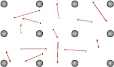
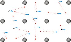
The arrows represent the random motion of the electrons. If the piece of metal is part of a circuit through which a current is flowing, then another motion is added to the random motion. This motion is more regular and results in a general movement of electrons through the metal.
The size of this movement depends on the current, the type of metal and the dimensions of the piece of metal.
The size of this movement depends on the current, the type of metal and the dimensions of the piece of metal.
The resistance of a piece of metal is due to collisions between the free electrons and the metal ions. The ions "get in the way" of the electrons and slow down their progress through the metal.
Resistance to the flow of current causes the temperature to increase. This resistance causes electrical energy to be converted into heat.
Task 3
Your teacher will provide you with a selection of objects (metals and non-metals). Construct a basic circuit which includes a light bulb.
Replace one of the connectors with each of the objects and record your observations in a table.
X
Task 4
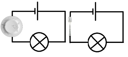
Circuit A has a porcelain plate to complete the circuit.
Circuit B has a metal spoon in to complete the
circuit.
Which circuit will complete to allow the bulb to light up? X
Give explanation to your answer.
X
Describe the function of components in a circuit
Task 5
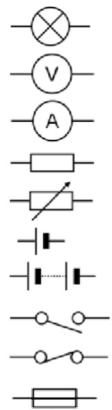
In circuit diagrams components are represented by the following symbols. Your teacher will provide you with a collection of components. Name each component and take a photo of one.
Which circuit will complete to allow the bulb to light up? X
Give explanation to your answer.
X
Describe the function of components in a circuit
Task 5
In circuit diagrams components are represented by the following symbols. Your teacher will provide you with a collection of components. Name each component and take a photo of one.
Describe and predict how current will flow through a circuit
An electric current is a flow of charged particles. The charge is already in the wires (carried by billions of tiny particles called ELECTRONS)
A current in a metal is due to the movement of electrons. In a conducting solution (electrolyte), the current is due to the movement of ions.
Current is measured using an ammeter.
An ammeter measures the rate of flow of charge. For simplicity, an ammeter can be thought of as a "counter of electrons": it gives a reading which is proportional to the number of electrons which pass through it per second.
The unit of current is the Ampere, A.
An ammeter is always connected in series with other components.
Task 6
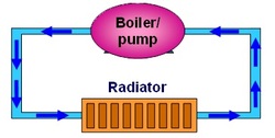
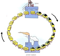
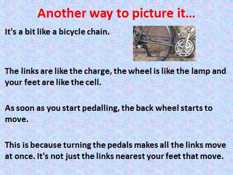
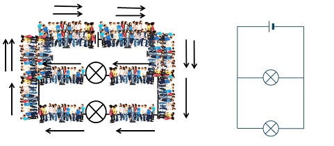
For each model of an electrical circuit, identify the part that represents: a) Battery, b) Wires, c) Current, d) Component (e.g. a bulb), e) Electrons
An electric current is a flow of charged particles. The charge is already in the wires (carried by billions of tiny particles called ELECTRONS)
A current in a metal is due to the movement of electrons. In a conducting solution (electrolyte), the current is due to the movement of ions.
Current is measured using an ammeter.
An ammeter measures the rate of flow of charge. For simplicity, an ammeter can be thought of as a "counter of electrons": it gives a reading which is proportional to the number of electrons which pass through it per second.
The unit of current is the Ampere, A.
An ammeter is always connected in series with other components.
Task 6
For each model of an electrical circuit, identify the part that represents: a) Battery, b) Wires, c) Current, d) Component (e.g. a bulb), e) Electrons
X
X
Draw simple series and parallel electrical circuits
Series Circuit
In a series circuit all the components are connected to form a simple loop. In a series circuit the components are connected end to end. The current is the same all the way around the circuit.
Task 7
Look at each of the following websites on circuit building; voltage and current:
http://phet.colorado.edu/en/simulation/circuit-construction-kit-dc
http://phet.colorado.edu/en/simulation/ohms-law
http://phet.colorado.edu/en/simulation/circuit-construction-kit-dc-virtual-lab
http://phet.colorado.edu/en/simulation/battery-resistor-circuit
http://www.cleo.net.uk/consultants_resources/science/circuitWorld/circuitworld.html
In a parallel circuit the components are connected side by side and not end to end. The current now has 2 paths it can flow along. The current divides, so that some flows through one lamp and some through the other. When we made a circuit with 2 bulbs connect in parallel both bulbs shine.
Describe and measure current and voltage in different circuits
CURRENT
Task 8
Highlight all mistakes in the following text, and then write out the correct versions.
Current is the amount of electricity flowing around a circuit. We measure current using an Amp. Current is measured in Volts. The current is the same anywhere in a circuit, so it does not matter where an ammeter goes in a circuit. Current is used up as it goes around the circuit.
Task 9
THE UNIT FOR CURRENT IS X
ITS SYMBOL IS X
AND IT IS MEASURED IN X
When we made a circuit with 2 bulbs connected in SERIES the current.
When there was one bulb connected the current was X amps
When there were 2 bulbs connected the current was X amps
Task 10
In this lesson you will investigate the current and voltage in parallel circuits to understand the advantages they have. First, your teacher will measure the current at various points in a series circuit.

|
A1 = X Amps
A2 = X Amps A3 = X Amps A4 = X Amps What have you found out about the current in a parallel circuit? X |
VOLTAGE
We measured the voltage in the circuit using a X. When we INCREASED the voltage, we are X the amount of ‘push’ of electric current. To measure voltage we must connect the voltmeter in X across the cell.
Task 11
Voltage is the measure of X X. It tells us how much ‘push’ is left in a circuit at any point. To measure this, we find the difference in push between two parts of a circuit using a X Because the voltmeter compares the ‘push’ in two different places, it must be placed in parallel across the circuit – it does not form part of the circuit itself.
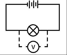
Next, you will need to measure the voltage in different places in the circuit. To do this, you need to place the voltmeter in the circuit at each of the places shown on this diagram (once before the bulb, once after). Record the readings on your voltmeter.
Task 12
THE UNIT FOR VOLTAGE / POTENTIAL DIFFERENCE IS X
ITS SYMBOL IS X
AND IT IS MEASURED IN X
Task 13
Task 12
THE UNIT FOR VOLTAGE / POTENTIAL DIFFERENCE IS X
ITS SYMBOL IS X
AND IT IS MEASURED IN X
Task 13
|
V1 = X Volts
V2 = X Volts V3 = X Volts What have you found out about the voltage in a series circuit? X |
Task 14
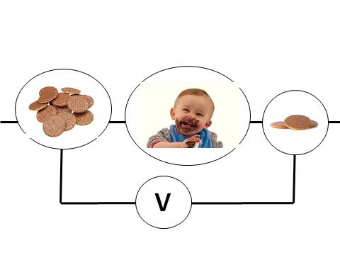
Interpret the following diagram.
Interpret the following diagram.
|
X
|
Task 15
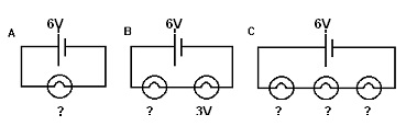
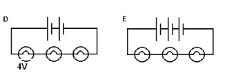
Below are some circuit diagrams. Your task is to work out the missing voltages.
Series Circuits
Below are some circuit diagrams. Your task is to work out the missing voltages.
Series Circuits
|
A = X
B = X C = X |
For Circuit D the voltage of the battery is 6V and for Circuit E the voltage of the battery is 18V.
|
D = X
E= X |
Task 16
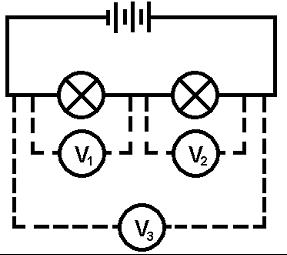
In this task you will investigate the current and voltage in parallel circuits to understand the advantages they have. To do this you will need to set up a parallel circuit. Start by constructing a circuit of two bulbs in parallel
Next, you will need to measure the voltage in different places in the circuit. To do this, you need to place the voltmeter in the circuit at each of the places shown on this diagram (once before the bulb, once after). Record the readings on your voltmeter.
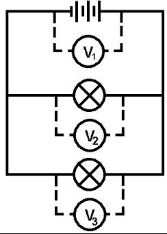
|
V1 = X Volts
V2 = X Volts V3 = X Volts What have you found out about the voltage in a parallel circuit? X |
Calculate power of components in a circuit
Any component which possesses resistance will convert electrical energy into heat energy.
The current, I, is a measure of the number of Coulombs of charge which pass through the resistor per second.
The voltage, V, is a measure of the number of Joules of energy lost by each Coulomb of charge passing through the resistor.
Therefore, the number of Joules of energy converted to heat by the resistor per second is given by energy per second = voltage × current We know that Power is a measure of how quickly energy is consumed / used up.
So, P = VI
Power = rate of doing work.
Unit of power = Watt (W) = Joules per second (Js-1)
EXAMPLE:
A toaster has the following information written on it:
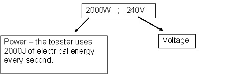
What does this mean?
If you use your toaster for 1 minute (60 seconds ) then the amount of electrical energy used is equal to 2000 x 60 = 120 000J.
The toaster uses 2000J of energy every second. So, in 60 seconds it would use X
Note: BRIGHTNESS = POWER
Task 18
Construct a circuit consisting of two light bulbs connected in parallel. Record the current and voltage readings for each of them. Use these readings to calculate the power of each light bulb. What do you expect?
Bulb 1
Voltage (V)
Current (I)
Power (P)
Bulb 2
Voltage (V)
Current (I)
Power (P)
Remove one of the light bulbs and use your voltage and current readings to verify that the brightness remained unchanged. Explain why.
X
